
![[Sintron] Arcade JAMMA Board Standard Cabinet Wiring Harness Loom 28*2 56pin Cable for Arcade Jamma Multigame Boards PCB Video Game Board - Sintron](http://sintron-hk.com/cdn/shop/products/51krhRd4EiL_{width}x.jpg?v=1527381764)
![[Sintron] Arcade JAMMA Board Standard Cabinet Wiring Harness Loom 28*2 56pin Cable for Arcade Jamma Multigame Boards PCB Video Game Board - Sintron](http://sintron-hk.com/cdn/shop/products/51lDnzO6z1L_{width}x.jpg?v=1527381764)
![[Sintron] Arcade JAMMA Board Standard Cabinet Wiring Harness Loom 28*2 56pin Cable for Arcade Jamma Multigame Boards PCB Video Game Board - Sintron](http://sintron-hk.com/cdn/shop/products/51krhRd4EiL_530x@2x.jpg?v=1527381764)
![[Sintron] Arcade JAMMA Board Standard Cabinet Wiring Harness Loom 28*2 56pin Cable for Arcade Jamma Multigame Boards PCB Video Game Board - Sintron](http://sintron-hk.com/cdn/shop/products/51krhRd4EiL_1024x1024@2x.jpg?v=1527381764)
![[Sintron] Arcade JAMMA Board Standard Cabinet Wiring Harness Loom 28*2 56pin Cable for Arcade Jamma Multigame Boards PCB Video Game Board - Sintron](http://sintron-hk.com/cdn/shop/products/51lDnzO6z1L_1024x1024@2x.jpg?v=1527381764)
Overview
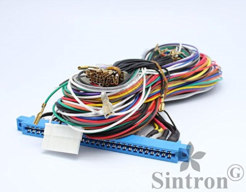
Please click the picture to enlarge the picture, then you will find, this is with great quality wires, not those cheap bad poor quality with 24 AWG or 26 AWG wires.
This is Brand new Jamma Harness with 2x28pins 56 Pin connector that can be used for standard Jamma Arcade cabinet (Machines) and PCBs.
This harness is ideal for replacing old harness in any old JAMMA cabinet or for customers who are bulding new machines with JAMMA boards.
All wiring uses 22AWG (22AWG is enough for Jamma PCB ), Cheaper harnesses will only use 24AWG or 26AWG or even (Marked with 22AWG but actually with 24 or 26 AWG quality ). The problem is if the resistance of wire is too high, it can cause a significant power loss before the DC voltages even reach the JAMMA PCB!
Please Notice
For Power Sections: (Pins A-F, 1-6, e, f, 27, 28)
When you are connecting power cables +5V +12V and -5V, please must double check before you connect them, if you connect them wrong, it's possible that you will get your jamma pcb damaged.
Wiring diagram
Below is the basic pinout diagram for jamma pcb, you can use this as reference when you are connecting the wire/ harness.

JAMMA Pinout Chart
Solder Side – Alpha Characters – 28 Pins – A-Z, a-f
The solder surface is the base surface of the PCB. It is the surface anywhere the soldered connections of lesser are bare to view. Few, if any, lesser are situated on the solder side. The solder surface pinout is recognized by means of alpha characters.
Component Side– Numeric Characters – 28 Pins – 1-28
The lesser surface is the top surface of the PCB. It is the surface anywhere the lesser are located. The lesser surface pinout is recognized by means of numeric characters.
Usually, the PCB is printed and the edge connector is embossed by means of the alpha and numeric characters.
GROUND – A, 1
GROUND – B, 2
+5VDC – C, 3
+5VDC – D, 4
-5VDC – E, 5
+12VDC – F, 6
KEY SLOT – H, 7
COIN COUNTER #2 – J
COIN COUNTER #1 – 8
LOCK OUT COIL #2 – K
LOCK OUT COIL #1 – 9
SPEAKER (-) – L
SPEAKER (+) – 10
N/C – M
N/C – 11
VIDEO GREEN – N
VIDEO RED – 12
VIDEO SYNC – P
VIDEO BLUE – 13
SERVICE SWITCH – R
If you base what you do on inaccurate information, you might be unpleasantly surprised by the consequences. Make sure you get the whole “Understanding the JAMMA PCB and Edge Connector Pinout” story from informed sources.
VIDEO GROUND – 14
TILT (SLAM) SWITCH – S
TEST SWITCH – 15
COIN SWITCH #2 – T
COIN SWITCH #1 – 16
PLAYER 2 – START – U
PLAYER 1 – START – 17
PLAYER 2 – UP – V
PLAYER 1 – UP – 18
PLAYER 2 – DOWN – W
PLAYER 1 – DOWN – 19
PLAYER 2 – LEFT – X
PLAYER 1 – LEFT – 20
PLAYER 2 – RIGHT – Y
PLAYER 1 – RIGHT – 21
PLAYER 2 – BUTTON 1 – Z
PLAYER 1 – BUTTON 1 – 22
PLAYER 2 – BUTTON 2 – a
PLAYER 1 – BUTTON 2 – 23
PLAYER 2 – BUTTON 3 – b
PLAYER 1 – BUTTON 3 – 24
N/C – c
N/C – 25
N/C – d
N/C – 26
GROUND – e
GROUND – 27
GROUND -f
GROUND – 28
Understanding the JAMMA Pinout Chart:
N/C – No connection.
Key Slot – A keyed slot construct aligns by means of a leave-out in the pinout part of the PCB.
This security characteristic is ,advertising to promise so as to the Power Section seats at the right end of the pinout section. If the edge connector is reversed, and the Power Section is seated at the conflicting or wrong end, irreparable damaged can occur to the PCB.
If the key has person’s name removed as of the edge connector, after that mark the connector as to the “Parts Side” to assist promise right seating.
Power Section – Pins A-F, 1-6, e, f, 27, 28
Video Section – Pins N, P, 13-15
Coin Section – Pins J, K, T, 8, 9, 16
Controller (Joystick) Section – Pins V-Y, 18-21
Pushbutton Switch Section – Pins Z-B, 22-24
Knowing enough about “Understanding the JAMMA PCB and Edge Connector Pinout” to make solid, informed choices cuts down on the fear factor. If you apply what you’ve just learned about “Understanding the JAMMA PCB and Edge Connector Pinout”, you should have nothing to worry about.
Notice:
For Power Sections: (Pins A-F, 1-6, e, f, 27, 28)
When you are connecting power cables +5V +12V and -5V , please must double check before you connect them , if you connect them wrong , it's possible that you will get your jamma pcb damaged.
The Package included
For more parts, you can also check our store maker-diy.com